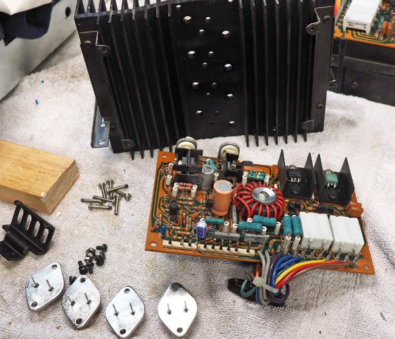
The output sections get the typical
work-over. The components are checked,
pots cleaned, PCB scrubbed, and a new set
of caps are installed. After reassembly, I set
these aside to tackle the main supply cap
problem.
work-over. The components are checked,
pots cleaned, PCB scrubbed, and a new set
of caps are installed. After reassembly, I set
these aside to tackle the main supply cap
problem.
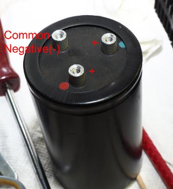
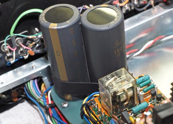
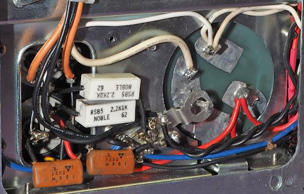
Below, is the original supply capacitor. It is two capacitors in
one can. These types of caps are just not produced today.
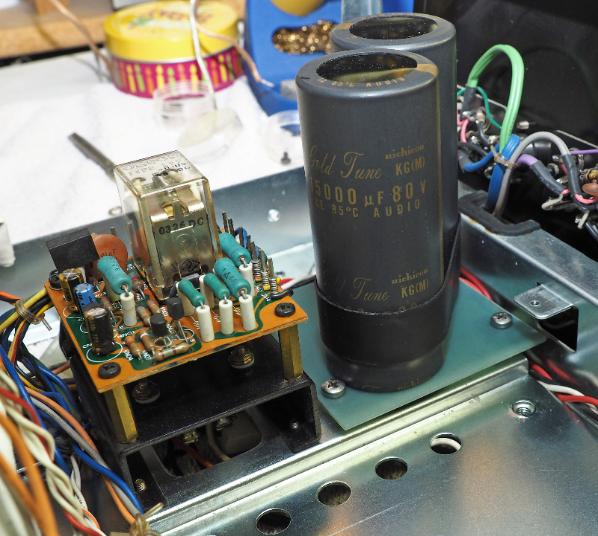
I etched a custom PCB to mount two 15,000uf Nichicon Fine
Gold caps on. It was a tight fit for the space, but I was able to
find a mounting position that also allowed for the PCB to use
the original mounting clamp screw holes.
The PCB is a heavy Mil spec fiberglass reinforced board. I
picked up a handful of this heavy (2oz) clad board at a
company auction that produced equipment for the military. The
board is thick and stiff and the copper clad is 2oz (70um). A 1/4"
wide trace is like laying 20ga. wire across the board. It's perfect
for mounting large caps like these.
After etching, the trace is covered with a thin layer of solder,
and the board is mounted on nylon spacers to isolate it from
the chassis. Last, the capacitor are soldered to the PCB and the
wiring is reworked.
one can. These types of caps are just not produced today.
I etched a custom PCB to mount two 15,000uf Nichicon Fine
Gold caps on. It was a tight fit for the space, but I was able to
find a mounting position that also allowed for the PCB to use
the original mounting clamp screw holes.
The PCB is a heavy Mil spec fiberglass reinforced board. I
picked up a handful of this heavy (2oz) clad board at a
company auction that produced equipment for the military. The
board is thick and stiff and the copper clad is 2oz (70um). A 1/4"
wide trace is like laying 20ga. wire across the board. It's perfect
for mounting large caps like these.
After etching, the trace is covered with a thin layer of solder,
and the board is mounted on nylon spacers to isolate it from
the chassis. Last, the capacitor are soldered to the PCB and the
wiring is reworked.
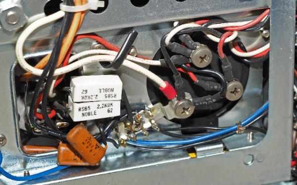
The reworked capacitor and PCB is pictured here along with
the original set up for comparison. It all worked out nicely. I
believe the wiring is cleaner.
NEXT PAGE
the original set up for comparison. It all worked out nicely. I
believe the wiring is cleaner.
NEXT PAGE